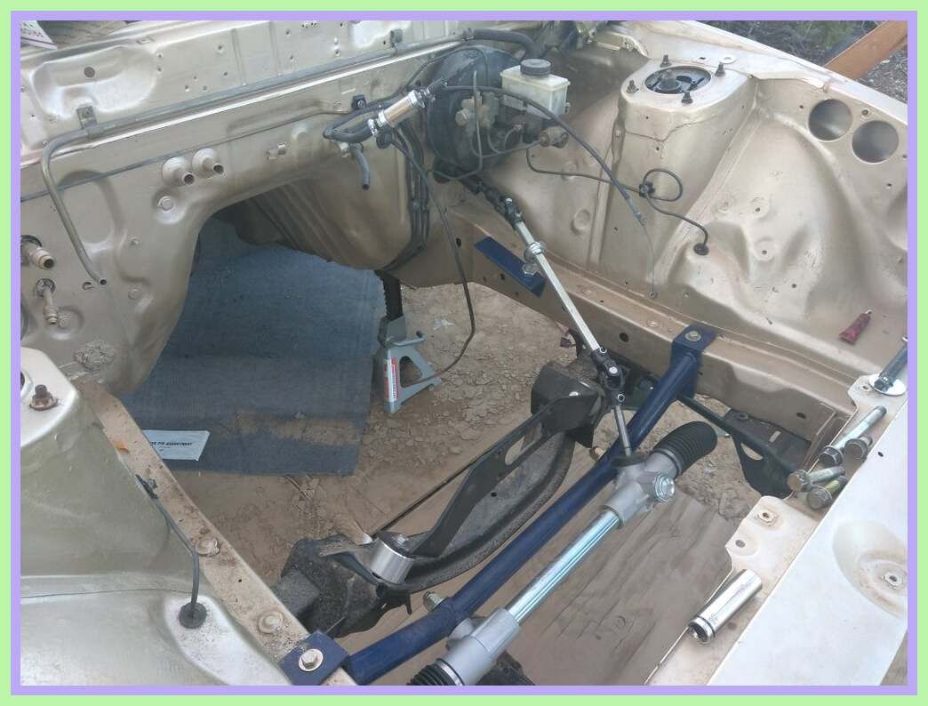
Simple Rack And Pinion Steering Diagram

Helical gearing gives smoother and quieter operation for the driver.
Simple rack and pinion steering diagram. A simplified rack and pinion steering diagram showing the column 2 rack and pinion 3 and tie rod 4 image via wikimedia commons laurensvanlieshout a tie rod links the rack to the kingpin. Rack and pinion steering is quickly becoming the most common type of steering on cars small trucks and suvs. A typical rack and pinion steering layout showing how the rack acts directly on the road wheel steering arms. It also provides a gear reduction so turning the wheels is easier.
This pinion runs in mesh with a rack that is connected to the steering tie rods. It is actually a pretty simple mechanism. A rack and pinion gearset is enclosed in a metal tube with each end of the rack protruding from the tube. The steering system converts the rotation of the steering wheel into a swivelling movement of the road wheels in such a way that the steering wheel rim turns a long way to move the road wheels a short way.
The rack and pinion steering box has a pinion connected to the steering column. Both the pinion and the rack teeth are helical gears. Rack and pinion steering uses a gear set to convert the circular motion of the steering wheel into the linear motion required to turn the wheels. A rod called a tie rod connects to each end of the rack.


