Single Phase Energy Meter Phasor Diagram
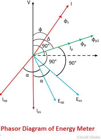
What Is Energy Meter Definition Construction Working Theory Circuit Globe

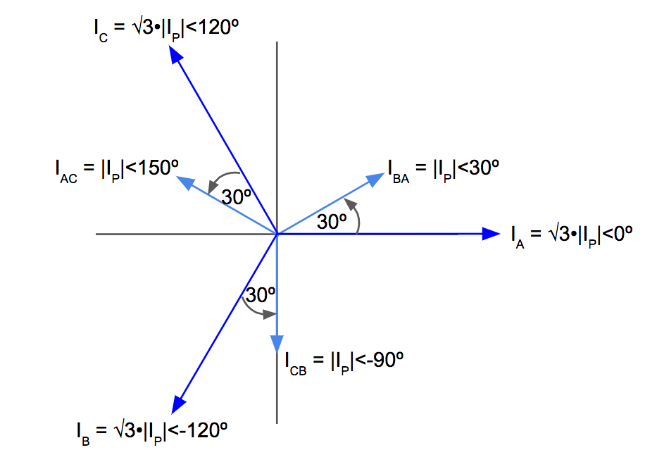
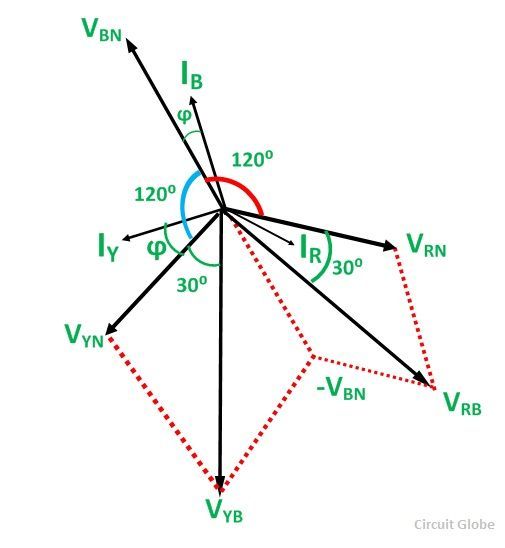
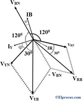
Three Phase Transformer Connections Phasor Diagrams Transformers Connection Diagram

Diagram Single Phase Phasor Diagram Full Version Hd Quality Phasor Diagram Chartdiagram Lineakebap It
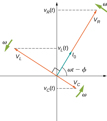
15 4 Rlc Series Circuits With Ac Physics Libretexts
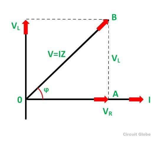
What Is Rl Series Circuit Phasor Diagram Power Curve Circuit Globe
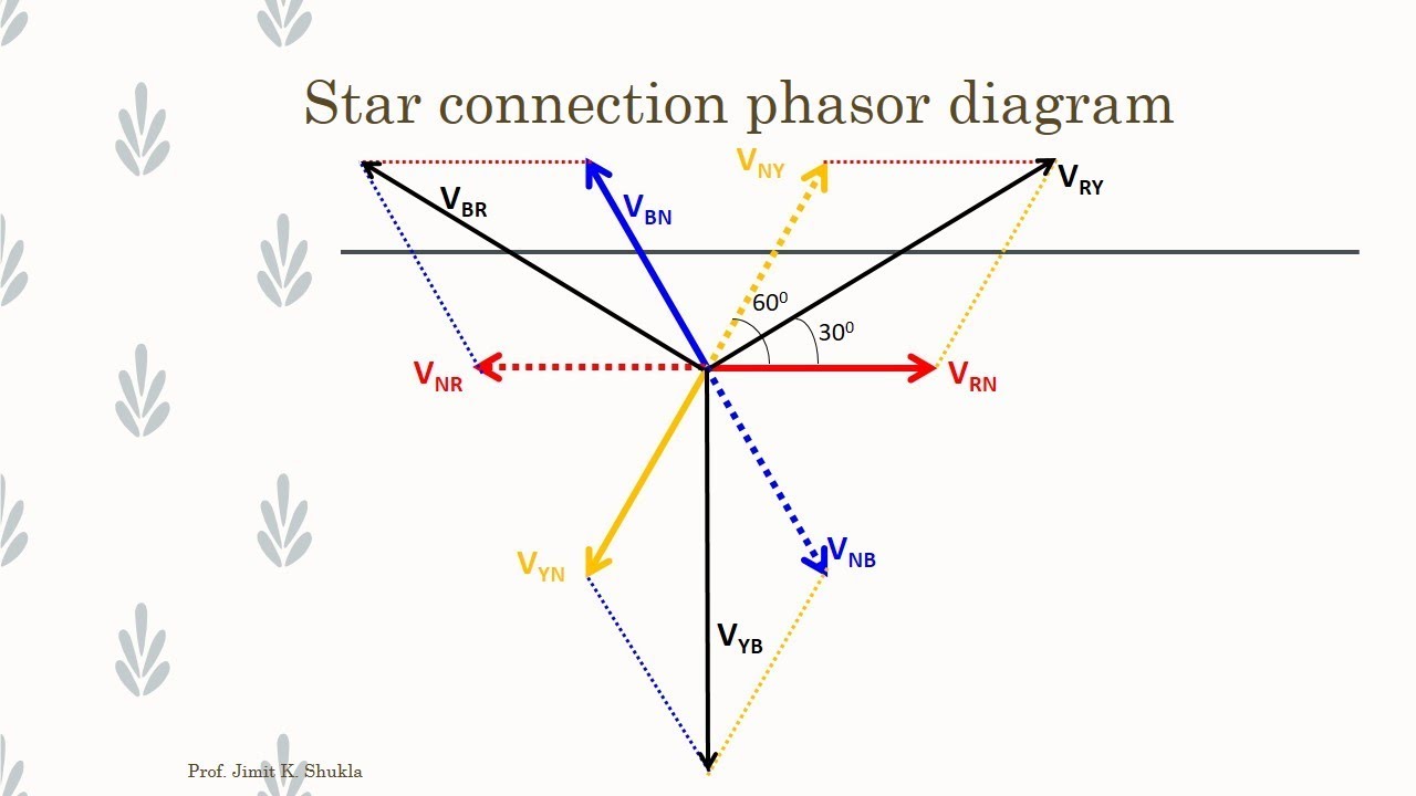
Diagram Electrical Phasor Diagram Full Version Hd Quality Phasor Diagram Chartdiagram Lineakebap It

This is the meter that most people will find on their homes.
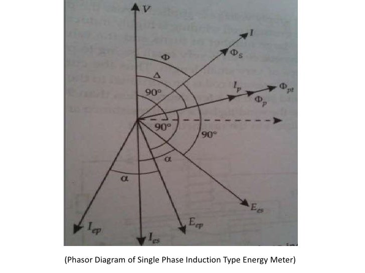
Single phase energy meter phasor diagram. In diagram i use red coler wire for line phase and black for neutral. When the energy meter is connected in circuit the current coil carries the load current and pressure coil carries the current proportional to the supply voltage. This form is also used for many small businesses as well. Phasor diagram of single phase induction type energy meter 6.
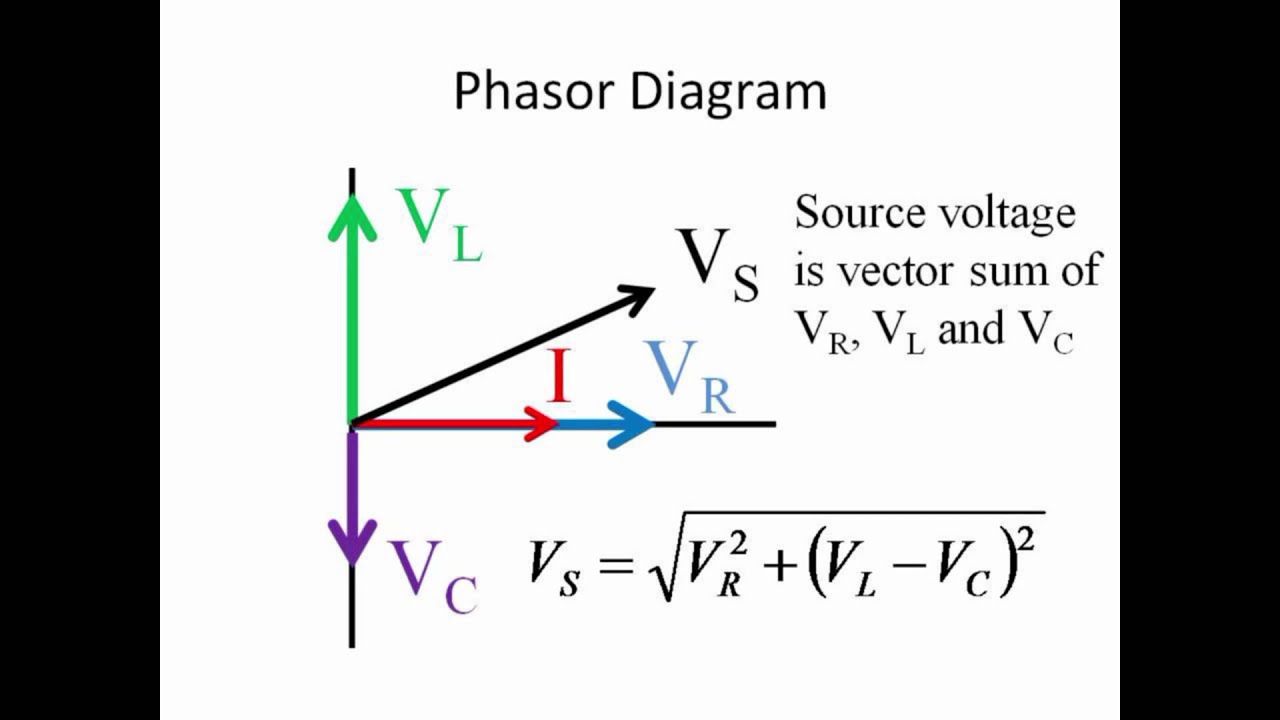
They are the. The phase of an alternating quantity at any instant in time can be represented by a phasor diagram so phasor diagrams can be thought of as functions of time. Theory operation working 5. This meter is most commonly used in a 240v single phase three wire service.
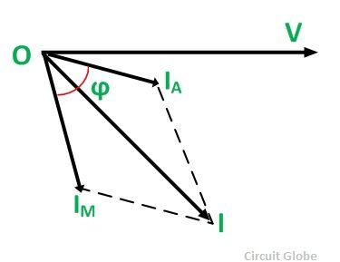
The magnetic field produced by series magnetic in phase with the line current and magnetic field produced by shunt magnet is in quadrature with the applied voltage thus a phase difference exists between the fluxes produce by the two. Here we are going to discuss the single phase induction type in detail. Below energy meter diagram i shown a single phase kwh meter with incoming supply and out going supply to home collage shop etc. The energy meter has four main parts.
To calibrate the given energy meter using a calibrated wattmeter. Construction driving system moving system braking syatem and registering system 4. Form 3s meters are typically used for single phase two wire services where the service is so. Introduction single phase induction meter 3.
S no equipment range type quantity 1 variac single phase 10 a ac 2 voltmeter 300 v ac 3 ammeter 0 10a ac 4 rheostat ac 5 wattmeter lpf ac 6 single phase energy meter 10a ac theory. The phasor diagram of the energy meter is shown in the figure below. Single phase induction type energy meter is also popularly known as watt hour meter. This name is given to it.
Click here for a form 2s meter wiring diagram. In the above diagram i shown an utility pole form which i get supply to kilowatt hour e meter and after that i get supply form energy meter. Three phase type induction meters. The construction of the single phase energy meter is shown in the figure below.
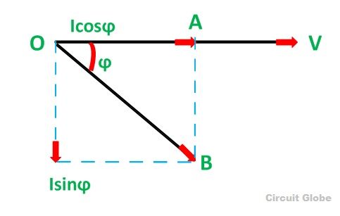
A complete sine wave can be constructed by a single vector rotating at an angular velocity of ω 2πƒ where ƒ is the frequency of the waveform. Calibration and testing of single phase energy meter aim.

Phasor Diagram For The Interfering Fields Top And The Resulting Power Download Scientific Diagram
Gps Signal Phasor Diagram Describing Carrier Tracking Loop Operation Download Scientific Diagram
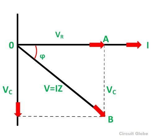
What Is Rc Series Circuit Phasor Diagram And Power Curve Circuit Globe

Phasor Diagrams For Amplitude Left Panel And Phase Right Panel Download Scientific Diagram

Figure A 1 Two Axis Synchronous Machine Phasor Diagram Download Scientific Diagram

Capacitor Phasor Diagram 12 13 Download Scientific Diagram

Data Logger Power Factor Meter Power Quality Analyzer Three Phase Power Monitor

Measurement Of Reactive Power By Single Wattmeter Method Electrical Technology And Industrial Practice

1 Phasor Diagram
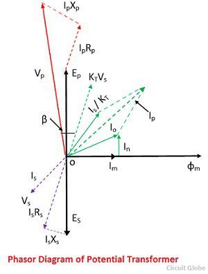
What Is Potential Transformer Pt Definition Construction Types Errors Phasor Diagram Applications Circuit Globe
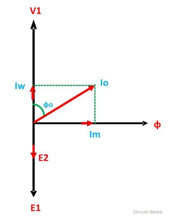
Transformer On No Load Condition Its Phasor Diagram Circuit Globe

3b Phasor Diagram For Three Wire Network With Y Connected Transformers Download Scientific Diagram

Phasor Diagram In The Complex Domain Showing The Phase Deviation Download Scientific Diagram
Open Delta Transformer Connection Electrical Pe Review

Analysis Of The Equivalent Circuit Induction Machines With Images Single Phase Transformer Transformer Construction Circle Diagram
Phasor Diagram Of The Cascade Ptc Figure 4 B Shows The Amplitude Download Scientific Diagram
Two Wattmeter Method Balanced Load Condition Circuit Globe

Potential Transformer Construction Working Theory Phasor Diagram Errors Characteristics
1

Nw 2263 Phasor Diagram Of Induction Motor Your Electrical Home Download Diagram
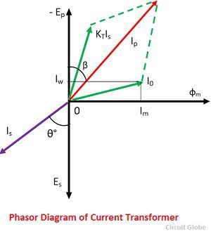
What Is Current Transformer Ct Definition Construction Phasor Diagram Types Circuit Globe
Two Wattmeter Method Construction Derivation Its Applications
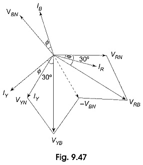
Power Factor By Two Wattmeter Method
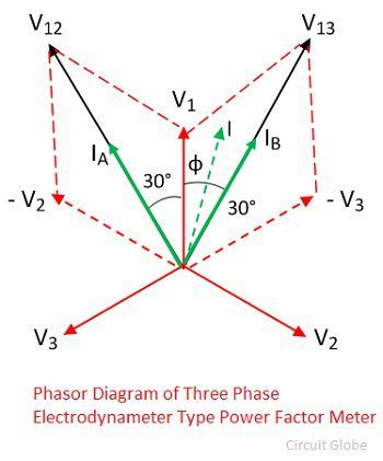
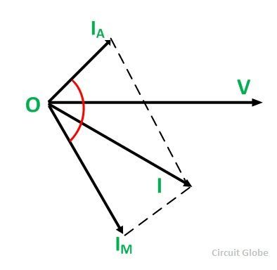
What Is Power Factor Meter Definition Types Circuit Globe
Phasor Diagram Of An Ideal Transformer Single Phase Transformer Diagram Transformers
Capacitor Start Induction Motor Its Phasor Diagram Characteristic Applications Circuit Globe
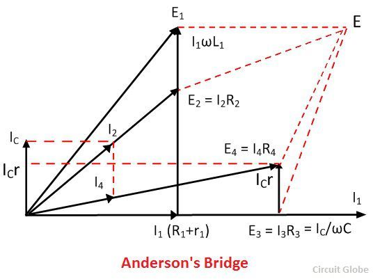
What Is Anderson S Bridge Definition Construction Phasor Diagram Theory Advantages Disadvantages Circuit Globe
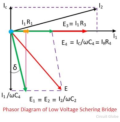
What Is Schering Bridge High Voltage Schering Bridge Measurment Of Relative Permeability Circuit Globe
Lab7 Physics Labs
Hay S Bridge Circuit Theory Phasor Diagram Advantages Applications Electrical4u
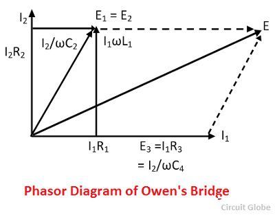
What Is Owen S Bridge Definition Phasor Diagram Theory Advantages Disadvantages Circuit Globe

Phasor Diagram For Standing Acoustic Wave In Open Open Tube Download Scientific Diagram

Phasor Diagram For Harmonic Current And Voltage Separation Download Scientific Diagram

Hydro Power Plant Electrical Article In 2020 Hydro Power Plant Power Plant Hydro

Phasor Diagram Of Transformer At Unity Power Factor Youtube
What Is Active Reactive And Apparent Power Definition And Explanation Circuit Globe

Short Transmission Line Phasor Diagram Performance Electrical4u
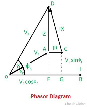
What Is Short Transmission Line Its Phasor Diagram Abcd Parameters Circuit Globe
What Is A Split Phase Induction Motor Its Applications Circuit Globe
Rl Series Circuit Analysis Phasor Diagram Examples Derivation Electrical4u

Ac Capacitance And Capacitive Reactance In Ac Circuit

Per Phase Equivalent Circuit And Phasor Diagrams Describing The Download Scientific Diagram